
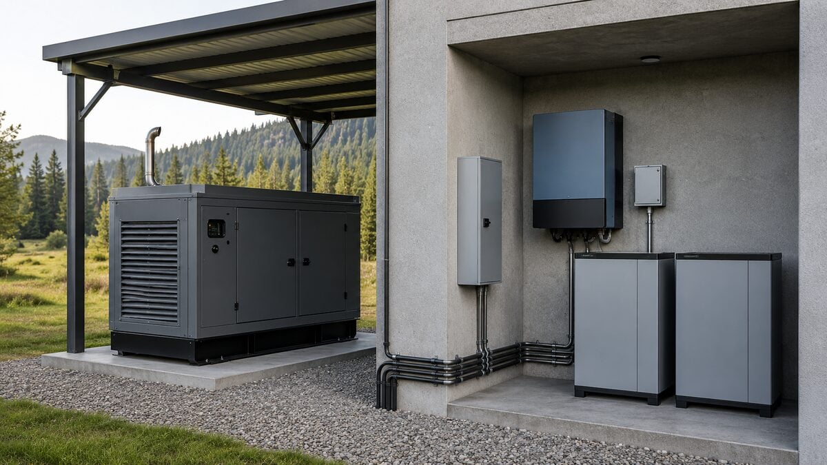
An off-grid generator auto-start system can restore charging before a
battery bank reaches a critical state. The control concept looks simple:
the inverter or energy controller requests a start, the generator runs,
and the charger replenishes the batteries. A reliable installation still
depends on compatible control signals, correct charging limits, sensible
start and stop thresholds, and careful commissioning.
This guide explains the two-wire start sequence for diesel generators
that use a controller such as the DynaGen
TG350. It also shows where AC and DC generator systems differ.
Always follow the manuals and wiring drawings for the exact inverter,
generator controller, battery system, and generator package in the
installation.
What two-wire generator
start means
A two-wire start interface usually uses a maintained contact. The
energy system closes the contact when it wants the generator to run and
opens the contact when it wants the generator to stop. The generator
controller then manages the engine sequence, including preheat when
configured, cranking, retry logic, warmup, protection, cooldown, and
shutdown.
The phrase “two-wire” describes the start command, not the entire
generator connection. The system may still need control power, fused
conductors, an interposing relay, status feedback, an emergency stop
circuit, and the normal power wiring between the generator and the
inverter charger or DC bus.
The TG350
controller manufacturer lists manual, remote, and automatic start
functions. The installer must still configure the correct input and
confirm how the Aurora generator package uses that input. Do not assume
that a terminal number from another generator or an online diagram
applies to your unit.
How the
complete start and charge sequence works
A typical AC generator and inverter charger installation follows this
sequence:
- The inverter, automatic generator start module, or site controller
detects a valid start condition. - Its dry contact closes, or its powered auxiliary output energizes an
approved relay. - The generator controller detects the remote start request and begins
its programmed engine sequence. - The generator reaches stable voltage and frequency.
- The inverter charger qualifies the incoming AC source, connects it,
and begins charging within its programmed current limit. - The generator supplies the charger and any permitted site
loads. - The energy controller reaches the stop condition and removes the
start request. - The generator controller completes any configured cooldown and stops
the engine.
Schneider Electric describes this general arrangement for its XW
Pro and Conext Automatic Generator Start system. Other inverter
brands use different terminals, settings, and logic, so the installer
must use the correct manufacturer documentation.
Confirm signal
compatibility before wiring
Start by identifying the inverter output and the generator controller
input. These signals commonly fall into two groups:
- Dry contact output: A relay contact opens or closes
without supplying voltage. - Powered auxiliary output: The inverter supplies a
control voltage, often 12 volts, when it requests a start.
Never apply external voltage to an input that expects only a dry
contact. If the inverter provides a powered output and the controller
expects a contact closure, use a correctly rated interposing relay. The
relay can also provide electrical isolation and protect the inverter
output from an incompatible circuit.
Check the following items before connecting conductors:
- Output type, voltage, and maximum contact or current rating
- Generator controller input type and input programming
- Required fuse and conductor size for the control circuit
- Relay coil voltage and contact rating when the system requires a
relay - Whether the generator must remain in Auto mode to accept the
signal - Whether the installation needs run, fault, or available status
feedback
OutBack’s Radian
installation documentation provides a useful example of why this
check matters. Some installations use a relay auxiliary output, while
others use a powered auxiliary output and additional equipment. That
distinction changes the control circuit even when both systems support
automatic generator start.
Set
start and stop logic that protects the battery and generator
The start signal should respond to a sustained energy shortage, not
every short load surge. Use battery state of charge from a compatible
shunt or battery management system when the equipment supports it.
Battery voltage can still serve as a trigger, but load, temperature,
battery chemistry, and cable voltage drop can affect the reading.
Build the control logic around these functions:
- Start threshold: Select a state of charge or
voltage that leaves enough reserve for the generator to start and
stabilize. - Start delay: Require the low condition to persist
before starting. This prevents a large motor or brief inverter surge
from starting the generator unnecessarily. - Stop threshold: Stop after the system reaches the
chosen state of charge, charge stage, or voltage condition. Follow
battery manufacturer guidance. - Minimum run time: Give the engine enough time to
warm up and perform useful charging work. - Restart delay: Prevent rapid stop and restart
cycles. - Quiet hours: Use them only when the available
battery reserve can safely support the restricted period.
For example, an installer might start a system at 30 percent state of
charge after a time delay and stop near 80 percent after a minimum run
period. Those values only illustrate the logic. Battery chemistry, site
loads, seasonal solar production, charger behavior, and manufacturer
limits determine the actual settings.
Limit
charger demand to the generator’s usable capacity
Automatic start does not guarantee that the generator can support the
charger at its maximum setting. The charger, site loads, power factor,
altitude, ambient temperature, and transient demands all affect the
required generator capacity.
Program the inverter charger’s AC input and charging limits so the
combined demand stays within the generator package rating and the
applicable breaker rating. Schneider’s XW Pro
commissioning guidance specifically includes generator input
settings and generator breaker size. Other manufacturers use different
menus and definitions.
Aurora often suggests selecting and loading a generator so it
typically operates near 70 percent of its rated output during sustained
charging. That target often gives a diesel engine a practical balance of
fuel efficiency, operating temperature, transient reserve, and
continuous operation. It is a planning target, not a universal rating
rule. Always confirm the generator’s prime, standby, or continuous
rating, the engine manufacturer’s load guidance, site derating, and the
actual electrical load. Avoid planning for routine operation at 100
percent of a standby rating.
The recent Aurora article on generator
overload when charging batteries explains how charger demand and
other loads can combine to overload a generator. For additional system
sizing context, compare DC
and AC generator approaches for battery charging.
AC and DC
generator systems use different power paths
An AC generator normally feeds the inverter charger’s generator
input. The inverter qualifies the AC waveform and controls battery
charging. Its input limit therefore plays a central role in generator
loading.
A DC generator connects to the battery system or DC bus through
equipment designed for that purpose. It may use the same type of
two-wire start request, but it does not send charging power through the
inverter’s AC generator input. The DC generator controller and battery
system must coordinate charging voltage, current, temperature
compensation, stop logic, and battery management system permissions.
Direct DC charging can reduce conversion steps in some off-grid
systems. It does not make every battery bank or inverter compatible.
Review Aurora’s solar
and DC generator integration guide and the available 24
VDC 6 kW diesel generator and 48
VDC 6 kW diesel generator as starting points. Aurora must confirm
the final application, battery voltage, charging profile, controls, and
communications.
Common auto-start problems
The generator does not crank
Confirm that the generator controller is in Auto mode, the remote
start input changes state, the emergency stop circuit is healthy, and
the starting battery has adequate voltage. Then inspect fuses, relays,
input programming, and controller fault history.
The
generator starts but the inverter rejects AC power
Check generator voltage and frequency, warmup time, inverter input
limits, neutral and grounding design, and the inverter’s accepted AC
range. Do not widen protection settings merely to hide an unstable
generator output.
The generator starts
and stops too often
Increase the start delay, add enough separation between start and
stop thresholds, confirm the state of charge source, and set a suitable
minimum run time. Also check whether a large intermittent load is
creating false low-voltage events.
Charging overloads the
generator
Reduce the inverter charging limit and account for all loads that
remain connected while charging. Verify the generator rating type and
any altitude or temperature derating. Measure actual current on each leg
instead of relying only on software estimates.
The
batteries charge, but the generator never stops
Check the stop trigger, battery monitor synchronization, charge stage
settings, minimum run timer, and the remote start contact. Confirm that
the controller sees the start input open when the energy system requests
a stop.
Commission
the system before leaving it unattended
Use a controlled test plan:
- Confirm every control connection against the current equipment
drawings. - Test manual generator operation and correct existing engine or
electrical faults first. - Verify the remote start request with the generator output
disconnected from the inverter charger when the manufacturer procedure
permits it. - Confirm stable generator voltage and frequency before applying
charging load. - Start with a conservative charging limit and measure generator
loading. - Test normal stop, cooldown, restart delay, and loss of the start
signal. - Simulate low battery, high load, generator fault, and emergency stop
conditions safely. - Record final settings, wire labels, test results, and controller
configuration for service technicians.
A qualified installer must also address overcurrent protection,
transfer equipment, neutral and grounding requirements, ventilation,
fuel supply, exhaust, and local electrical and building rules. Two-wire
control does not replace those requirements.
Build
the control strategy around the whole energy system
A dependable off-grid generator auto-start system needs more than two
conductors. Match the signal types, configure stable start and stop
logic, limit charger demand, and test every operating state. These steps
help the generator perform useful charging work without frequent cycling
or avoidable overload.
Aurora Generators can help review the generator rating, battery
voltage, inverter charger, start interface, site loads, and controller
requirements for a new or existing system. Contact Aurora
Generators with the equipment model numbers and a basic one-line
diagram before ordering or changing the control wiring.