
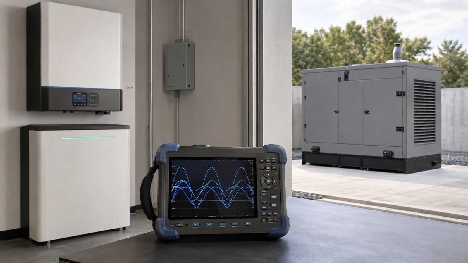
Modern battery inverter systems have changed the diesel generator’s role.
In many off-grid and hybrid systems, the generator no longer powers the building directly for long periods. Instead, it starts periodically, supplies the site’s loads and provides substantial additional power to an inverter-charger to recharge a battery bank.
This arrangement can work extremely well. But it also creates an electrical interaction that many people misunderstand.
A generator may produce a clean 120/240 V, 60 Hz sine wave with low total harmonic distortion until an inverter-charger begins drawing power. Once charging starts, the waveform may develop notches, flattened sections or narrow spikes. Instruments may suddenly report unusually high voltage. Generator controllers can issue overvoltage alarms. An inverter may repeatedly accept and reject generator power.
The immediate conclusion is often: “The generator is producing bad power.”
That conclusion may be wrong.
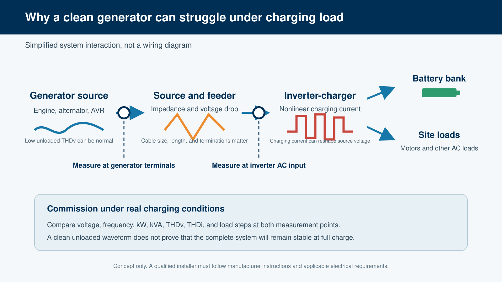
A modern inverter-charger is a power-electronic, nonlinear load. The current it draws from the generator can itself contain harmonics and high-frequency switching components. Those currents flow through the alternator and distribution system impedance and can distort the voltage measured at the generator terminals.
This distinction is not unique to Aurora Generators. Eaton, Cummins, STAMFORD/AvK, Caterpillar, ABB, Schneider Electric and Leroy-Somer all publish engineering guidance describing different aspects of this same phenomenon.
A generator can contribute to the magnitude of voltage distortion without being the source of the harmonic current that caused it.
A simple example
Imagine a 25 kW diesel generator operating at 240 V. Before the inverter connects, the voltage is 240 V, the frequency is 60.0 Hz, the voltage THD is low, and the waveform is a clean sine wave.
Now connect a large battery inverter-charger. The generator engine speed remains stable, and the AVR is still regulating, but the voltage waveform develops repetitive distortion or narrow spikes. A meter or controller may now report an apparent voltage considerably higher than 240 V.
What changed? The load changed.
The most important equation in this article
For each harmonic frequency:
Vh = Ih × Zh
Vh is harmonic voltage, Ih is harmonic current, and Zh is source/system impedance at that harmonic frequency.
A nonlinear inverter can create harmonic current. The generator has finite electrical impedance. When harmonic current flows through that impedance, it creates harmonic voltage.
This also explains why the same inverter may operate normally on utility power, behave poorly on a 25 kW generator and appear to operate normally again on a 100 kW generator.
What Eaton says
Eaton provides one of the clearest real-world examples. In its harmonics case studies, a 40 kW standby generator supplied a facility containing multiple UPS systems.
On utility power, voltage distortion was approximately 3%. When the generator supplied power and the UPS battery chargers began recharging, Eaton reports voltage distortion increased to nearly 22%. The UPS systems rejected the distorted generator voltage and returned to battery. Once the chargers disconnected, the nonlinear load disappeared, the generator waveform improved, and the UPS systems attempted to reconnect.
The significance is important: the equipment rejecting the distorted voltage was also producing the harmonic current that interacted with the generator source impedance.
Eaton’s generator harmonics guidance further explains that generator source impedance is generally higher than a utility source. The same harmonic current can therefore create more voltage distortion on generator power.
What Cummins says
Cummins states in Specifying Standby Generator Set Requirements for Data Centers that harmonic voltage distortion depends on load-generated current distortion and source impedance.
Generator subtransient reactance, X″d, is an important part of that source impedance. Different alternator sizes can therefore show different terminal-voltage distortion while supplying the same nonlinear load. A stiffer source changes the response to the harmonic current. It does not change which load produced that current.
What STAMFORD/AvK says
STAMFORD/AvK’s official AGN-025: Non-Linear Loads considers nonlinear-load harmonic current together with alternator reactance and the resulting harmonic voltage distortion.
This is particularly useful evidence because STAMFORD is an alternator manufacturer. Harmonic voltage can appear at an alternator’s terminals because load-generated harmonic current is flowing through the alternator’s impedance. The location where distorted voltage is measured is not necessarily where the harmonic current originates.
What Caterpillar says
Caterpillar’s Generator System Installation Considerations identifies battery chargers and UPS equipment as nonlinear loads. Caterpillar also discusses increased alternator capacity to handle harmonic-current heating and limit voltage distortion by reducing alternator reactance.
This explains why an inverter may appear to work correctly on a much larger generator. The larger alternator is a stiffer electrical source, so the same harmonic current produces less voltage distortion. That is a valid engineering observation, but it does not prove the smaller generator was producing inherently poor-quality power.
What ABB says
ABB’s Back-up Generators and Harmonics explains that current distortion causes voltage distortion and that utility power is normally a stiffer, lower-impedance source than a generator.
ABB gives an example where the same load produces about 2.25% voltage distortion on utility power and 4.10% on generator power. The load did not change. The source impedance changed.
ABB also discusses distorted waveforms interfering with sensing and control. That matters when a controller or meter suddenly indicates excessive voltage after an inverter connects even though the fundamental 60 Hz voltage has not risen by the same amount.
What Schneider Electric says
Schneider Electric’s Origin of Harmonics describes nonlinear loads as sources of harmonic currents that flow upstream through the electrical network. Schneider expresses the relationship as Uh = Zh × Ih. For a given harmonic current, greater source impedance means greater harmonic voltage distortion.
Schneider also publishes guidance on determining the source of harmonic distortion by comparing current and voltage harmonic measurements. The lesson is simple: don’t point fingers first. Measure current and voltage simultaneously.
What Leroy-Somer says
Leroy-Somer’s technical guidance on alternator sizing with nonlinear loads considers the load harmonic spectrum, allowable voltage distortion and alternator reactance when selecting an alternator.
Again, the system-level relationship is the same. The nonlinear load determines the harmonic current it demands; the source characteristics determine how much voltage distortion results.
Why utility, a smaller generator and a larger generator can behave differently
Consider the exact same inverter-charger drawing the exact same distorted current from three sources:
- Utility: very low source impedance, therefore relatively little voltage distortion.
- 25 kW generator: higher source impedance relative to the load, therefore greater voltage distortion.
- 100 kW generator: lower relative impedance, therefore less voltage distortion.
Same inverter. Same harmonic current. Different source impedance. Different voltage distortion.
This is why “it works on a much larger generator” is useful diagnostic information, but not proof of a defect in the smaller generator.
What the waveforms actually tell us
Clean sine wave
With the inverter disconnected, a healthy generator should produce a smooth repeating waveform within its published voltage, frequency and THDv specifications. This is the baseline.
Low-order harmonic distortion
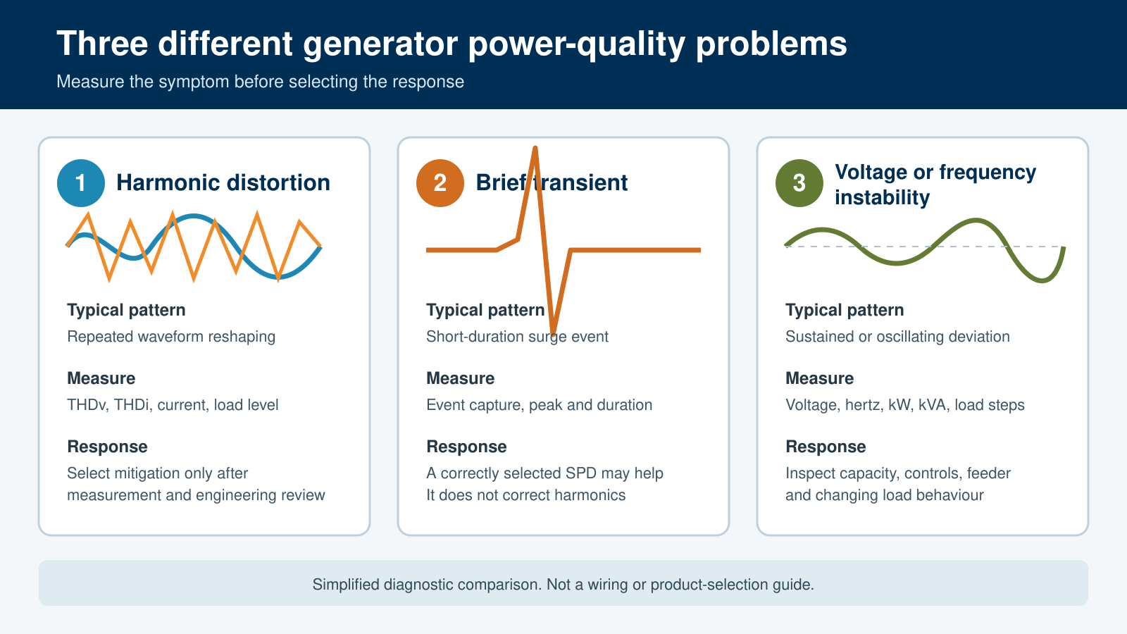
If the sine wave becomes consistently flattened or reshaped at the same points on every cycle after charging begins, measure THDi and THDv simultaneously. If current distortion increases with charging load and voltage distortion follows it, that is strong evidence of load/source interaction.
Voltage notching
Regular notches in the waveform can occur during power-electronic commutation. Their depth depends on both the electronic load and the impedance feeding it.
High-frequency spikes or ringing
Narrow spikes riding on the sine wave may contain frequencies far above the conventional 5th, 7th, 11th and 13th harmonics used in many generator-sizing discussions. Switching transitions, EMI, cable inductance and capacitance or resonant interaction can be involved.
This distinction matters because a low-order harmonic filter may do little for high-frequency switching noise. Differential-mode or common-mode EMI filtering may be more appropriate. An oscilloscope and frequency-spectrum measurement are especially valuable here.
Why a controller may report “high voltage”
Suppose the fundamental generator voltage remains approximately 240 V but narrow high-frequency peaks appear after the inverter begins charging. Depending on the sensing circuit, bandwidth and algorithm, a controller or meter may respond disproportionately to those peaks and display an apparent 255 V, 270 V or other overvoltage.
That does not necessarily mean the AVR has raised the 60 Hz fundamental voltage to that value.
Before adjusting an AVR, compare true RMS voltage, the 60 Hz fundamental component, peak voltage, THDv, waveform and frequency spectrum. Otherwise, lowering the AVR to make one instrument reading look normal could leave the actual fundamental voltage too low.
This is not automatically conventional power factor
Traditional power factor discussions describe current leading or lagging the 60 Hz voltage. That is displacement power factor. Nonlinear inverter-chargers introduce distortion power factor: fundamental current can be nearly in phase with voltage while the overall current waveform contains significant harmonics.
A conventional capacitor bank is therefore not the default solution and can create harmonic resonance if applied without analysis. For inverter-generator troubleshooting, record true PF, displacement PF (where available), THDi, THDv, kW, and kVA.
Why Victron often works better with generators
Aurora has seen good field compatibility with Victron systems. More importantly, Victron’s published design and configuration features give objective engineering reasons why its inverter-chargers can integrate more easily with finite generator sources. This does not mean every Victron model will work with every generator without correct sizing and setup.
AC input-current limiting and PowerControl
Victron lets the installer limit how much current a generator can supply. PowerControl reduces battery charging as other AC loads consume available source capacity. A large inverter may be capable of very high charging power, but that does not mean the generator should be forced to provide it.
Dynamic Current Limiter
Victron’s MultiPlus generator guidance documents Dynamic Current Limiter behaviour intended for generator sources. Instead of imposing a large, abrupt load step, generator loading can increase more progressively, giving the engine governor, turbocharger, alternator field, and AVR time to respond.
PowerAssist
PowerAssist can temporarily use battery/inverter power to supplement the generator when site demand exceeds the programmed AC input limit. The generator therefore does not have to carry the entire transient instantaneously.
Weak AC
Victron documents a Weak AC mode for difficult incoming waveforms. It changes charger behaviour so the unit can tolerate a more distorted source. Victron also documents the tradeoff: input power factor can become worse, increasing generator kVA demand. It is a compatibility tool, not a substitute for correct system design.
Generator-specific configuration and firmware
Victron provides configurable source acceptance, charging limits and generator-related settings rather than assuming every AC source behaves like a stiff utility bus. Victron has also released firmware changes specifically intended to improve stability with certain generator combinations.
Generator compatibility can be deliberately engineered into an inverter. A terminal labelled GEN does not by itself establish good generator compatibility.
Aurora’s generator-compatible inverter buying checklist
Before buying an inverter that will regularly charge from a generator, ask:
- What generator voltage THD can the inverter tolerate?
- What THDi does the charger produce at roughly 25%, 50%, 75% and 100% charging power?
- What is the charger’s true input power factor?
- Does it use active PFC or active input-current shaping?
- Can AC input current be limited independently of inverter output capacity?
- Can charging power ramp gradually after the generator connects?
- Does it have a dedicated generator operating mode?
- Can you configure voltage and frequency acceptance windows?
- Can the battery temporarily support large AC load steps?
- What minimum generator kW and kVA are recommended for this exact model?
- Does the manufacturer specify maximum source impedance or alternator X″d?
- Has the inverter been tested with conventional synchronous diesel generators?
- Does the manufacturer permit or recommend a line reactor, harmonic filter or EMI filter?
- Does it publish generator commissioning and troubleshooting documentation?
A specification saying only “generator THD must be below 3%” describes the quality the inverter expects to receive. It does not tell the designer what harmonic current the inverter sends back into the generator source. Both sides of the interface matter.
How Aurora would diagnose the problem
Test A: generator only
Measure THDv, voltage, frequency and waveform.
Test B: generator plus conventional load
Apply a substantial resistive or otherwise well-behaved load and repeat the measurements.
Test C: inverter at low charging current
Connect the inverter with a conservative AC input-current or battery-charge limit. Measure both voltage and current waveforms.
Test D: increase charging in controlled steps
At each level, record THDv, THDi, true RMS voltage, fundamental voltage, peak voltage, frequency, amps, kW, kVA, true PF, displacement PF where available, voltage waveform and current waveform.
Test E: substitute another inverter
If generator alone is clean, generator plus conventional load is clean, one known inverter operates acceptably, but another inverter reproducibly creates severe distortion, that is technically meaningful. It does not automatically prove the second inverter is defective, but it makes a blanket claim of poor generator quality difficult to support without additional evidence.
What to ask an inverter manufacturer that says it is the generator
- What generator THDv limit has been exceeded?
- What maximum source impedance is permitted?
- What alternator X″d is acceptable?
- What minimum generator kVA is required?
- What THDi does the inverter produce at the actual charging level?
- What amount of voltage notching or high-frequency noise is acceptable?
- Does the charger use active PFC? (Power Factor Correction)
- Is an input line reactor recommended?
- Is a passive or active harmonic filter recommended?
- Is an EMI filter recommended for high-frequency switching components?
- Which published generator specification has the connected generator failed?
How to fix it
1. Reduce inverter charging current
This is one of the fastest diagnostic tests. If THDv, apparent overvoltage, or instability falls substantially when you reduce charging current, the interaction is strongly related to inverter input demand.
2. Enable generator-specific inverter controls
Use manufacturer-approved input-current limits, generator modes, softer load ramps and source-acceptance settings. Do not simply widen protection limits until alarms disappear.
3. Check the AC feeder
Long cables, undersized conductors, poor connections and transfer equipment add impedance. Measure at both the generator and inverter input under charging load.
4. Consider a properly selected line reactor
A line reactor adds controlled series inductance. It can reduce sharp current changes and some harmonic current and partially isolate a generator from a difficult power-electronic input stage. This is often a reasonable external mitigation to investigate before a costly active filter.
5. Measure the harmonic spectrum
Determine whether the problem is predominantly low-order harmonics or high-frequency switching noise before selecting a filter.
6. Passive harmonic filter
Passive filters can attenuate selected harmonic components, but choose them based on actual current-spectrum measurements.
7. EMI/common-mode/differential-mode filtering
If oscilloscope measurements show narrow high-frequency spikes or ringing, investigate appropriate EMI filtering rather than assuming a conventional harmonic filter will solve the problem.
8. Active harmonic filter
An active harmonic filter measures harmonic current and injects compensating current so the upstream generator sees a cleaner current waveform. It can be highly effective but may be difficult to justify economically for a single modest-size inverter system until simpler measures have been tested.
9. Larger alternator or generator
A larger alternator can lower effective source reactance and reduce resulting voltage distortion. Caterpillar, Cummins and alternator manufacturers recognize this approach. It is a system-design solution, not evidence by itself that the original generator was poor quality.
A fair standard for judging the generator
The generator deserves investigation if THDv is excessive before the inverter connects, voltage or frequency regulation is poor under conventional loads within rating, the alternator is incorrectly sized for the specified nonlinear load, AVR or excitation behaviour is abnormal, comparable generators perform materially better under the same controlled test, or the generator fails its published electrical specifications.
Conversely, if the generator produces low THDv before the inverter connects, remains stable under conventional loads, operates successfully with other inverter systems, becomes distorted only when one particular inverter begins charging, and shows progressively greater distortion as that inverter’s charging current increases, describing the problem simply as “poor generator quality” is not supported by the available evidence.
The more technically accurate description is a compatibility problem between a nonlinear inverter-charger and the generator source impedance.
Design the generator, inverter and battery as one system
The best installations are designed around the complete power path. Size the generator for simultaneous site load and realistic battery charging demand. Respect both kW and kVA. Preserve transient margin. Select an alternator appropriate for nonlinear loading. Keep feeder impedance under control. Choose an inverter with input-current management and documented generator support. Commission the system at the battery state of charge that creates the highest realistic charging demand.
If the generator’s primary purpose is charging a 24 V or 48 V battery bank, a purpose-built Aurora diesel DC generator can also eliminate the separate AC-generator-to-inverter-charger conversion stage where that architecture makes sense.
The key takeaway
A generator can influence how severely an inverter’s nonlinear current distorts AC voltage. That does not make the generator the source of the nonlinear current.
This distinction is supported independently by generator manufacturers, alternator manufacturers, and electrical-equipment manufacturers, including Eaton, Cummins, STAMFORD/AvK, Caterpillar, ABB, Schneider Electric, and Leroy-Somer.
Before replacing an AVR, installing an oversized generator or blaming either manufacturer, measure THDi and THDv together and look at the actual voltage and current waveforms.
The better question is not “Where do we see the distorted voltage?” It is “What equipment is generating the distorted current, and how is that current interacting with the source?”
Primary technical references
- Eaton: Harmonics Case Studies
- Eaton: Harmonics and Generators
- Cummins: Specifying Standby Generator Set Requirements for Data Centers
- STAMFORD/AvK: AGN-025 Non-Linear Loads
- Caterpillar: Generator System Installation Considerations
- ABB: Back-up Generators and Harmonics
- Schneider Electric: Origin of Harmonics
- Schneider Electric: Determining the Source of Harmonic Distortion
- Leroy-Somer: Alternator Sizing and Nonlinear Loads
- Victron Energy: MultiPlus Generator FAQ
Technical note: Compatibility depends on the exact generator, alternator, inverter model and firmware, system voltage, battery settings, feeder, grounding and bonding arrangement and connected loads. Power-quality measurements and electrical changes should be performed by qualified personnel using the manufacturers’ current instructions.
Modern battery inverter systems have changed the diesel generator’s role.
In many off-grid and hybrid systems, the generator no longer powers the building directly for long periods. Instead, it starts periodically, supplies the site’s loads and provides substantial additional power to an inverter-charger to recharge a battery bank.
This arrangement can work extremely well. But it also creates an electrical interaction that many people misunderstand.
A generator may produce a clean 120/240 V, 60 Hz sine wave with low total harmonic distortion until an inverter-charger begins drawing power. Once charging starts, the waveform may develop notches, flattened sections or narrow spikes. Instruments may suddenly report unusually high voltage. Generator controllers can issue overvoltage alarms. An inverter may repeatedly accept and reject generator power.
The immediate conclusion is often: “The generator is producing bad power.”
That conclusion may be wrong.
A modern inverter-charger is a power-electronic, nonlinear load. The current it draws from the generator can itself contain harmonics and high-frequency switching components. Those currents flow through the alternator and distribution system impedance and can distort the voltage measured at the generator terminals.
This distinction is not unique to Aurora Generators. Eaton, Cummins, STAMFORD/AvK, Caterpillar, ABB, Schneider Electric and Leroy-Somer all publish engineering guidance describing different aspects of this same phenomenon.
A generator can contribute to the magnitude of voltage distortion without being the source of the harmonic current that caused it.
A simple example
Imagine a 25 kW diesel generator operating at 240 V. Before the inverter connects, the voltage is 240 V, the frequency is 60.0 Hz, the voltage THD is low, and the waveform is a clean sine wave.
Now connect a large battery inverter-charger. The generator engine speed remains stable, and the AVR is still regulating, but the voltage waveform develops repetitive distortion or narrow spikes. A meter or controller may now report an apparent voltage considerably higher than 240 V.
What changed? The load changed.
The most important equation in this article
For each harmonic frequency:
Vh = Ih × Zh
Vh is harmonic voltage, Ih is harmonic current, and Zh is source/system impedance at that harmonic frequency.
A nonlinear inverter can create harmonic current. The generator has finite electrical impedance. When harmonic current flows through that impedance, it creates harmonic voltage.
This also explains why the same inverter may operate normally on utility power, behave poorly on a 25 kW generator and appear to operate normally again on a 100 kW generator.
What Eaton says
Eaton provides one of the clearest real-world examples. In its harmonics case studies, a 40 kW standby generator supplied a facility containing multiple UPS systems.
On utility power, voltage distortion was approximately 3%. When the generator supplied power and the UPS battery chargers began recharging, Eaton reports voltage distortion increased to nearly 22%. The UPS systems rejected the distorted generator voltage and returned to battery. Once the chargers disconnected, the nonlinear load disappeared, the generator waveform improved, and the UPS systems attempted to reconnect.
The significance is important: the equipment rejecting the distorted voltage was also producing the harmonic current that interacted with the generator source impedance.
Eaton’s generator harmonics guidance further explains that generator source impedance is generally higher than a utility source. The same harmonic current can therefore create more voltage distortion on generator power.
What Cummins says
Cummins states in Specifying Standby Generator Set Requirements for Data Centers that harmonic voltage distortion depends on load-generated current distortion and source impedance.
Generator subtransient reactance, X″d, is an important part of that source impedance. Different alternator sizes can therefore show different terminal-voltage distortion while supplying the same nonlinear load. A stiffer source changes the response to the harmonic current. It does not change which load produced that current.
What STAMFORD/AvK says
STAMFORD/AvK’s official AGN-025: Non-Linear Loads considers nonlinear-load harmonic current together with alternator reactance and the resulting harmonic voltage distortion.
This is particularly useful evidence because STAMFORD is an alternator manufacturer. Harmonic voltage can appear at an alternator’s terminals because load-generated harmonic current is flowing through the alternator’s impedance. The location where distorted voltage is measured is not necessarily where the harmonic current originates.
What Caterpillar says
Caterpillar’s Generator System Installation Considerations identifies battery chargers and UPS equipment as nonlinear loads. Caterpillar also discusses increased alternator capacity to handle harmonic-current heating and limit voltage distortion by reducing alternator reactance.
This explains why an inverter may appear to work correctly on a much larger generator. The larger alternator is a stiffer electrical source, so the same harmonic current produces less voltage distortion. That is a valid engineering observation, but it does not prove the smaller generator was producing inherently poor-quality power.
What ABB says
ABB’s Back-up Generators and Harmonics explains that current distortion causes voltage distortion and that utility power is normally a stiffer, lower-impedance source than a generator.
ABB gives an example where the same load produces about 2.25% voltage distortion on utility power and 4.10% on generator power. The load did not change. The source impedance changed.
ABB also discusses distorted waveforms interfering with sensing and control. That matters when a controller or meter suddenly indicates excessive voltage after an inverter connects even though the fundamental 60 Hz voltage has not risen by the same amount.
What Schneider Electric says
Schneider Electric’s Origin of Harmonics describes nonlinear loads as sources of harmonic currents that flow upstream through the electrical network. Schneider expresses the relationship as Uh = Zh × Ih. For a given harmonic current, greater source impedance means greater harmonic voltage distortion.
Schneider also publishes guidance on determining the source of harmonic distortion by comparing current and voltage harmonic measurements. The lesson is simple: don’t point fingers first. Measure current and voltage simultaneously.
What Leroy-Somer says
Leroy-Somer’s technical guidance on alternator sizing with nonlinear loads considers the load harmonic spectrum, allowable voltage distortion and alternator reactance when selecting an alternator.
Again, the system-level relationship is the same. The nonlinear load determines the harmonic current it demands; the source characteristics determine how much voltage distortion results.
Why utility, a smaller generator and a larger generator can behave differently
Consider the exact same inverter-charger drawing the exact same distorted current from three sources:
- Utility: very low source impedance, therefore relatively little voltage distortion.
- 25 kW generator: higher source impedance relative to the load, therefore greater voltage distortion.
- 100 kW generator: lower relative impedance, therefore less voltage distortion.
Same inverter. Same harmonic current. Different source impedance. Different voltage distortion.
This is why “it works on a much larger generator” is useful diagnostic information, but not proof of a defect in the smaller generator.
What the waveforms actually tell us
Clean sine wave
With the inverter disconnected, a healthy generator should produce a smooth repeating waveform within its published voltage, frequency and THDv specifications. This is the baseline.
Low-order harmonic distortion
If the sine wave becomes consistently flattened or reshaped at the same points on every cycle after charging begins, measure THDi and THDv simultaneously. If current distortion increases with charging load and voltage distortion follows it, that is strong evidence of load/source interaction.
Voltage notching
Regular notches in the waveform can occur during power-electronic commutation. Their depth depends on both the electronic load and the impedance feeding it.
High-frequency spikes or ringing
Narrow spikes riding on the sine wave may contain frequencies far above the conventional 5th, 7th, 11th and 13th harmonics used in many generator-sizing discussions. Switching transitions, EMI, cable inductance and capacitance or resonant interaction can be involved.
This distinction matters because a low-order harmonic filter may do little for high-frequency switching noise. Differential-mode or common-mode EMI filtering may be more appropriate. An oscilloscope and frequency-spectrum measurement are especially valuable here.
Why a controller may report “high voltage”
Suppose the fundamental generator voltage remains approximately 240 V but narrow high-frequency peaks appear after the inverter begins charging. Depending on the sensing circuit, bandwidth and algorithm, a controller or meter may respond disproportionately to those peaks and display an apparent 255 V, 270 V or other overvoltage.
That does not necessarily mean the AVR has raised the 60 Hz fundamental voltage to that value.
Before adjusting an AVR, compare true RMS voltage, the 60 Hz fundamental component, peak voltage, THDv, waveform and frequency spectrum. Otherwise, lowering the AVR to make one instrument reading look normal could leave the actual fundamental voltage too low.
This is not automatically conventional power factor
Traditional power factor discussions describe current leading or lagging the 60 Hz voltage. That is displacement power factor. Nonlinear inverter-chargers introduce distortion power factor: fundamental current can be nearly in phase with voltage while the overall current waveform contains significant harmonics.
A conventional capacitor bank is therefore not the default solution and can create harmonic resonance if applied without analysis. For inverter-generator troubleshooting, record true PF, displacement PF (where available), THDi, THDv, kW, and kVA.
Why Victron often works better with generators
Aurora has seen good field compatibility with Victron systems. More importantly, Victron’s published design and configuration features give objective engineering reasons why its inverter-chargers can integrate more easily with finite generator sources. This does not mean every Victron model will work with every generator without correct sizing and setup.
AC input-current limiting and PowerControl
Victron lets the installer limit how much current a generator can supply. PowerControl reduces battery charging as other AC loads consume available source capacity. A large inverter may be capable of very high charging power, but that does not mean the generator should be forced to provide it.
Dynamic Current Limiter
Victron’s MultiPlus generator guidance documents Dynamic Current Limiter behaviour intended for generator sources. Instead of imposing a large, abrupt load step, generator loading can increase more progressively, giving the engine governor, turbocharger, alternator field, and AVR time to respond.
PowerAssist
PowerAssist can temporarily use battery/inverter power to supplement the generator when site demand exceeds the programmed AC input limit. The generator therefore does not have to carry the entire transient instantaneously.
Weak AC
Victron documents a Weak AC mode for difficult incoming waveforms. It changes charger behaviour so the unit can tolerate a more distorted source. Victron also documents the tradeoff: input power factor can become worse, increasing generator kVA demand. It is a compatibility tool, not a substitute for correct system design.
Generator-specific configuration and firmware
Victron provides configurable source acceptance, charging limits and generator-related settings rather than assuming every AC source behaves like a stiff utility bus. Victron has also released firmware changes specifically intended to improve stability with certain generator combinations.
Generator compatibility can be deliberately engineered into an inverter. A terminal labelled GEN does not by itself establish good generator compatibility.
Aurora’s generator-compatible inverter buying checklist
Before buying an inverter that will regularly charge from a generator, ask:
- What generator voltage THD can the inverter tolerate?
- What THDi does the charger produce at roughly 25%, 50%, 75% and 100% charging power?
- What is the charger’s true input power factor?
- Does it use active PFC or active input-current shaping?
- Can AC input current be limited independently of inverter output capacity?
- Can charging power ramp gradually after the generator connects?
- Does it have a dedicated generator operating mode?
- Can you configure voltage and frequency acceptance windows?
- Can the battery temporarily support large AC load steps?
- What minimum generator kW and kVA are recommended for this exact model?
- Does the manufacturer specify maximum source impedance or alternator X″d?
- Has the inverter been tested with conventional synchronous diesel generators?
- Does the manufacturer permit or recommend a line reactor, harmonic filter or EMI filter?
- Does it publish generator commissioning and troubleshooting documentation?
A specification saying only “generator THD must be below 3%” describes the quality the inverter expects to receive. It does not tell the designer what harmonic current the inverter sends back into the generator source. Both sides of the interface matter.
How Aurora would diagnose the problem
Test A: generator only
Measure THDv, voltage, frequency and waveform.
Test B: generator plus conventional load
Apply a substantial resistive or otherwise well-behaved load and repeat the measurements.
Test C: inverter at low charging current
Connect the inverter with a conservative AC input-current or battery-charge limit. Measure both voltage and current waveforms.
Test D: increase charging in controlled steps
At each level, record THDv, THDi, true RMS voltage, fundamental voltage, peak voltage, frequency, amps, kW, kVA, true PF, displacement PF where available, voltage waveform and current waveform.
Test E: substitute another inverter
If generator alone is clean, generator plus conventional load is clean, one known inverter operates acceptably, but another inverter reproducibly creates severe distortion, that is technically meaningful. It does not automatically prove the second inverter is defective, but it makes a blanket claim of poor generator quality difficult to support without additional evidence.
What to ask an inverter manufacturer that says it is the generator
- What generator THDv limit has been exceeded?
- What maximum source impedance is permitted?
- What alternator X″d is acceptable?
- What minimum generator kVA is required?
- What THDi does the inverter produce at the actual charging level?
- What amount of voltage notching or high-frequency noise is acceptable?
- Does the charger use active PFC? (Power Factor Correction)
- Is an input line reactor recommended?
- Is a passive or active harmonic filter recommended?
- Is an EMI filter recommended for high-frequency switching components?
- Which published generator specification has the connected generator failed?
How to fix it
1. Reduce inverter charging current
This is one of the fastest diagnostic tests. If THDv, apparent overvoltage, or instability falls substantially when you reduce charging current, the interaction is strongly related to inverter input demand.
2. Enable generator-specific inverter controls
Use manufacturer-approved input-current limits, generator modes, softer load ramps and source-acceptance settings. Do not simply widen protection limits until alarms disappear.
3. Check the AC feeder
Long cables, undersized conductors, poor connections and transfer equipment add impedance. Measure at both the generator and inverter input under charging load.
4. Consider a properly selected line reactor
A line reactor adds controlled series inductance. It can reduce sharp current changes and some harmonic current and partially isolate a generator from a difficult power-electronic input stage. This is often a reasonable external mitigation to investigate before a costly active filter.
5. Measure the harmonic spectrum
Determine whether the problem is predominantly low-order harmonics or high-frequency switching noise before selecting a filter.
6. Passive harmonic filter
Passive filters can attenuate selected harmonic components, but choose them based on actual current-spectrum measurements.
7. EMI/common-mode/differential-mode filtering
If oscilloscope measurements show narrow high-frequency spikes or ringing, investigate appropriate EMI filtering rather than assuming a conventional harmonic filter will solve the problem.
8. Active harmonic filter
An active harmonic filter measures harmonic current and injects compensating current so the upstream generator sees a cleaner current waveform. It can be highly effective but may be difficult to justify economically for a single modest-size inverter system until simpler measures have been tested.
9. Larger alternator or generator
A larger alternator can lower effective source reactance and reduce resulting voltage distortion. Caterpillar, Cummins and alternator manufacturers recognize this approach. It is a system-design solution, not evidence by itself that the original generator was poor quality.
A fair standard for judging the generator
The generator deserves investigation if THDv is excessive before the inverter connects, voltage or frequency regulation is poor under conventional loads within rating, the alternator is incorrectly sized for the specified nonlinear load, AVR or excitation behaviour is abnormal, comparable generators perform materially better under the same controlled test, or the generator fails its published electrical specifications.
Conversely, if the generator produces low THDv before the inverter connects, remains stable under conventional loads, operates successfully with other inverter systems, becomes distorted only when one particular inverter begins charging, and shows progressively greater distortion as that inverter’s charging current increases, describing the problem simply as “poor generator quality” is not supported by the available evidence.
The more technically accurate description is a compatibility problem between a nonlinear inverter-charger and the generator source impedance.
Design the generator, inverter and battery as one system
The best installations are designed around the complete power path. Size the generator for simultaneous site load and realistic battery charging demand. Respect both kW and kVA. Preserve transient margin. Select an alternator appropriate for nonlinear loading. Keep feeder impedance under control. Choose an inverter with input-current management and documented generator support. Commission the system at the battery state of charge that creates the highest realistic charging demand.
If the generator’s primary purpose is charging a 24 V or 48 V battery bank, a purpose-built Aurora diesel DC generator can also eliminate the separate AC-generator-to-inverter-charger conversion stage where that architecture makes sense.
The key takeaway
A generator can influence how severely an inverter’s nonlinear current distorts AC voltage. That does not make the generator the source of the nonlinear current.
This distinction is supported independently by generator manufacturers, alternator manufacturers, and electrical-equipment manufacturers, including Eaton, Cummins, STAMFORD/AvK, Caterpillar, ABB, Schneider Electric, and Leroy-Somer.
Before replacing an AVR, installing an oversized generator or blaming either manufacturer, measure THDi and THDv together and look at the actual voltage and current waveforms.
The better question is not “Where do we see the distorted voltage?” It is “What equipment is generating the distorted current, and how is that current interacting with the source?”
Primary technical references
- Eaton: Harmonics Case Studies
- Eaton: Harmonics and Generators
- Cummins: Specifying Standby Generator Set Requirements for Data Centers
- STAMFORD/AvK: AGN-025 Non-Linear Loads
- Caterpillar: Generator System Installation Considerations
- ABB: Back-up Generators and Harmonics
- Schneider Electric: Origin of Harmonics
- Schneider Electric: Determining the Source of Harmonic Distortion
- Leroy-Somer: Alternator Sizing and Nonlinear Loads
- Victron Energy: MultiPlus Generator FAQ
Technical note: Compatibility depends on the exact generator, alternator, inverter model and firmware, system voltage, battery settings, feeder, grounding and bonding arrangement and connected loads. Power-quality measurements and electrical changes should be performed by qualified personnel using the manufacturers’ current instructions.