
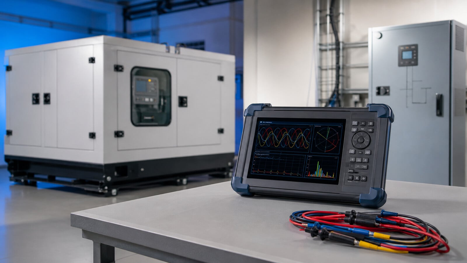
A generator can produce a clean voltage waveform with ordinary loads and then show distorted voltage as soon as an inverter, variable-frequency drive, UPS, charger, or other electronic load connects. That does not automatically mean the generator or the connected equipment is defective. Harmonic distortion often results from how the complete system interacts under load.
Understanding generator harmonic distortion starts with one important idea: many electronic devices do not draw current smoothly. Their pulsed current flows through the alternator’s internal impedance and the external impedance of cables, breakers, transfer equipment, and connections. The resulting voltage drop can reshape the voltage waveform seen by the generator controls and connected equipment.
What is harmonic distortion?
An ideal AC generator produces a smooth sine wave at its fundamental frequency, normally 60 Hz in Canada and the United States. A harmonic is a frequency at a whole-number multiple of that fundamental. On a 60 Hz system, the fifth harmonic is 300 Hz, and the seventh harmonic is 420 Hz.
Harmonic components combine with the fundamental waveform. The result may look flattened, notched, peaked, or otherwise different from a smooth sine wave. Engineers use a harmonic spectrum to identify the frequencies and magnitudes contributing to the shape.
Harmonic distortion is repetitive. Do not confuse it with a single brief voltage spike or a slower voltage or frequency change after a large load step.
What causes harmonics on a generator?
A linear load draws current that broadly follows the applied voltage waveform. A nonlinear load does not. It may draw most of its current during short portions of each AC cycle.
Common nonlinear loads include:
- Inverter-chargers and some battery chargers
- Variable-frequency drives and electronic motor controls
- Uninterruptible power supplies
- Rectifiers and AC-to-DC power converters
- Switch-mode computer and telecommunications power supplies
- LED drivers and other electronic lighting
- Welding equipment and industrial power electronics
STAMFORD’s nonlinear-load guidance explains that these loads draw current that does not mimic the applied voltage waveform. The harmonic current then distorts the supply voltage.

Why the generator voltage becomes distorted
The load creates much of the harmonic current, but the source and distribution system influence how much voltage distortion appears. A useful simplified relationship is:
Harmonic voltage distortion is influenced by harmonic current multiplied by system impedance.
Every alternator has internal impedance. Cables, transformers, breakers, transfer switches, connectors, and terminations add more. Harmonic current flowing through this combined impedance produces harmonic voltage drop. That voltage drop changes the waveform available to every connected load.
This helps explain why a larger generator sometimes appears to tolerate the same electronic load better than a smaller generator. The larger system may have lower effective source impedance relative to the load, more current capacity, a different excitation system, or more operating margin. Nameplate size alone does not prove compatibility, and it does not mean the smaller generator is poor quality.
THDv and THDi measure different things
Total harmonic distortion of voltage, or THDv, describes harmonic content in the voltage waveform. Total harmonic distortion of current, or THDi, describes harmonic content in the current waveform.
ABB’s harmonics application guide explains this distinction and notes that nonlinear current creates voltage harmonics through the electrical network. A load can have high THDi while the source maintains relatively low THDv. As the nonlinear load becomes large relative to the source, voltage distortion may increase.
THD percentages also need context. A high THDi value at very light current may have less system impact than a lower percentage at a much larger current. For facility-level current evaluation, engineers may also consider total demand distortion and the applicable point of common coupling. The proper metric depends on the question being investigated.
Low-order harmonics are not the same as switching noise
Traditional harmonic analysis focuses on integer multiples of 50 or 60 Hz, such as the third, fifth, seventh, eleventh, and thirteenth harmonics. These components commonly arise from rectifiers and other power-electronic input stages.
Inverters and switching power supplies also operate semiconductor switches at much higher frequencies. That high-frequency content can appear as ringing, sharp edges, or noise superimposed on the waveform. It may affect sensing circuits or communications without fitting neatly into a low-order harmonic explanation.
A standard THD reading may not capture every high-frequency event. The instrument bandwidth, sampling rate, probes, and recording method matter. A technician may need both harmonic analysis and an oscilloscope or power-quality analyzer with suitable transient and waveform capture capability.
Harmonics are different from voltage spikes and instability
- Harmonic distortion: A repetitive change in waveform shape caused by harmonic current and system interaction.
- Voltage transient or spike: A short-duration event caused by lightning, switching, contactor operation, or interruption of an inductive load.
- Voltage or frequency instability: A sustained deviation, oscillation, dip, or overshoot related to loading, engine governing, excitation, control settings, or repeated connection and disconnection.
A Type 1 or Type 2 surge protective device can help limit suitable brief transient events when correctly selected and installed. It does not remove harmonic current or regulate sustained voltage and frequency problems.
What can harmonic distortion do to equipment?
The result depends on the distortion’s magnitude and spectrum, duration, loading, system design, equipment susceptibility, and manufacturer limits. No single THD percentage predicts every failure. Possible effects include:
- Alternator heating: Harmonic currents can add winding, rotor, damper, and stray-load losses and reduce the capacity available for useful load.
- Transformer heating: Eddy-current and winding losses can increase, especially when a transformer supplies substantial nonlinear load.
- Neutral-current heating: Triplen harmonics from single-phase electronic loads can add in a shared neutral instead of cancelling.
- Motor heating and torque pulsation: Harmonic voltage can create additional losses, vibration, acoustic noise, and reduced motor efficiency.
- Cable and connection heating: Higher RMS current and frequency-dependent effects can increase losses.
- Capacitor stress: Harmonic current and resonance can overload power-factor-correction capacitors or tuned components.
- Nuisance alarms and trips: Drives, UPS systems, inverter-chargers, breakers, and generator controllers may reject distorted input or misinterpret peaks.
- Metering and sensing errors: Instruments that are not designed for distorted waveforms may report misleading voltage, current, power, or power factor.
- Electronic malfunction: Sensitive equipment may reset, flicker, overheat, disconnect, or operate unpredictably.
ABB’s technical guide to harmonics identifies heating in transformers, cables, motors, generators, and capacitors, along with nuisance trips, flicker, computer problems, and inaccurate metering as possible effects of excessive harmonic distortion.
Why measurements can differ across the same system
The generator terminals and inverter AC input are connected, but they are not electrically identical measurement points. Current flowing through the feeder creates voltage drop. Harmonic current creates harmonic voltage drop. A long cable, small conductor, transformer, loose termination, or switching device can change the waveform seen at the load.
Generator-terminal voltage may therefore differ from the voltage measured at the affected equipment. The difference can become more noticeable during rapid charging changes, motor starts, or inverter connection and disconnection.
For a useful comparison, measure both locations during the same operating sequence with synchronized or suitably time-correlated instruments. Do not compare readings taken on different days, at different load levels, or with different meter settings and assume the difference identifies a fault.
Generator design and operating conditions also matter
Several generator characteristics can influence the response to nonlinear loads:
- Alternator size relative to the nonlinear load
- Subtransient reactance and other manufacturer-specified impedance characteristics
- Winding pitch and alternator construction
- Excitation source and available excitation support
- AVR sensing method, response, and manufacturer-supported configuration
- Engine and governor response to changing real-power demand
- Connected linear load, which can sometimes improve the overall load mix
- Phase balance and neutral loading
- Altitude, temperature, enclosure airflow, and applicable duty rating
STAMFORD states that no single oversizing factor suits every nonlinear-load application. Consider the load’s harmonic current spectrum, total system load, alternator design, and acceptable voltage distortion together.
Nidec Leroy-Somer advises contacting technical support when applying its digital voltage regulator to nonlinear loads, transformer magnetization, or large load impacts. This reinforces the need for manufacturer-specific review rather than universal AVR settings.
Crest factor and rapid load changes add useful clues
Crest factor compares a waveform’s peak value with its RMS value. A current waveform made of narrow pulses can have high peaks even when its RMS current appears manageable. Those peaks can challenge the alternator, switching equipment, and sensing circuits.
An inverter-charger may also change its AC demand quickly as the battery state, charge stage, site load, or input-control algorithm changes. If the generator voltage moves outside the inverter’s acceptance window, the inverter may disconnect. The load then disappears, voltage recovers, and the inverter tries again. That repeating cycle may involve harmonics, control response, capacity, feeder impedance, or several factors at once.
Aurora’s article on generator and inverter compatibility examines this interaction in greater detail.
Measure before choosing a remedy
A qualified person should use a suitable power-quality analyzer and record the generator under repeatable operating conditions. Energized generator and distribution measurements involve shock, arc-flash, and mechanical hazards and are not a do-it-yourself procedure.
A practical measurement set may include:
- Voltage and frequency at no load and with a known linear load
- Voltage and current on every phase
- kW, kVA, kVAR, and true power factor
- THDv and THDi
- Individual harmonic spectrum
- Crest factor and waveform captures
- Voltage and current imbalance
- Load steps, motor starts, charging changes, and load removal
- Short-duration dips, swells, interruptions, and transients
- Readings at the generator terminals and affected equipment input
- Generator controller, inverter, drive, and UPS event logs
Record the generator model, alternator, AVR, voltage connection, phase, frequency, duty rating, site conditions, cable details, transformers, switching equipment, and exact connected-load models. Without that context, a THD number alone may lead to the wrong conclusion.
Ways to reduce generator harmonic distortion
The correct approach depends on the measured cause and the equipment involved. Useful options can include:
- Size the complete generator correctly: Check engine kW, alternator kVA, phase current, nonlinear-load capability, transient response, temperature, altitude, and duty rating.
- Provide realistic capacity margin: Avoid operating a small alternator near its limit with a large concentration of nonlinear load.
- Sequence loads: Prevent a charger ramp, large motor start, and other major load step from occurring simultaneously.
- Use conservative input settings: Where the equipment manufacturer permits, reduce generator-input current or charge current and increase it only after commissioning evidence supports the change.
- Balance phases: Distribute single-phase loads appropriately and check neutral current.
- Review the feeder: Have a qualified installer verify conductor sizing, terminations, connections, and excessive voltage drop.
- Reduce unnecessary impedance: Avoid needless feeder length or unsuitable components, while preserving all required protection and installation practices.
- Use manufacturer-supported chokes or reactors: An AC line reactor or DC-link choke can reduce some current harmonics in suitable drive or rectifier applications.
- Consider passive or active filters: These require harmonic measurements, system data, and appropriate engineering. They are not universal accessories.
- Select lower-harmonic equipment: Active power-factor correction, multi-pulse rectifiers, active-front-end drives, and other designs may reduce current distortion when correctly applied.
- Separate sensitive or disruptive loads: A dedicated source, transformer, feeder, or different system architecture may help when justified by engineering analysis.
- Consult both manufacturers: Generator and load-equipment manufacturers may identify supported settings, alternator selections, firmware, filters, or equipment changes.
Why common fixes are not interchangeable
A capacitor bank primarily addresses displacement power factor for suitable inductive loads. It does not cancel arbitrary harmonic current, and capacitors can interact with system inductance to create resonance.
A surge protective device limits certain short-duration overvoltage events. It does not correct sustained harmonic distortion.
A line reactor adds impedance. It can smooth current or reduce selected harmonics in an appropriate application, but it also creates voltage drop and changes the source-load interaction.
A passive filter targets a defined harmonic profile and can introduce reactive power or resonance if incorrectly applied. An active filter measures current and injects compensation, but it still requires correct sizing, placement, and system review.
Replacing the generator, alternator, inverter, charger, or drive may be justified in some cases, but replacement should follow measurements and manufacturer analysis. Guessing can move the symptom without solving the system problem.
Generator harmonic-distortion diagnostic checklist
- Identify the exact generator, alternator, AVR, controller, and nonlinear-load models.
- Record voltage, phase, frequency, duty rating, environmental conditions, and relevant manufacturer limits.
- Confirm the feeder, terminations, grounding, bonding, switching equipment, and protection through a qualified installer.
- Measure a no-load baseline and a known linear-load condition where appropriate.
- Connect the problem load in controlled steps and record current, kW, kVA, power factor, THDv, THDi, crest factor, and waveforms.
- Measure at the generator terminals and affected equipment input during the same event.
- Separate repetitive harmonics from brief transients and sustained voltage or frequency instability.
- Compare the harmonic spectrum and event logs with manufacturer guidance.
- Test conservative load limits or sequencing only when the equipment manufacturer supports it.
- Select reactors, filters, equipment changes, or generator changes only after the data identifies the problem.
- Repeat the same measurements after corrective work and document the result.
Never defeat protection, widen voltage or frequency limits by guesswork, bypass alarms, or alter grounding and bonding to force equipment to remain connected.
When to involve a specialist
A qualified electrician should examine feeders, terminations, switching equipment, grounding, bonding, protection, and site installation. The generator manufacturer should review alternator capability, excitation, AVR and governor behaviour, duty rating, and recorded generator data.
The inverter, UPS, charger, or drive manufacturer should confirm input limits, generator operating guidance, current-limit settings, firmware, and supported reactors or filters. A power-quality engineer is appropriate when several nonlinear loads interact, equipment continues to malfunction, the harmonic spectrum is complex, or mitigation requires a tuned passive filter or active-filter design.
Treat harmonic distortion as a system problem
Harmonics begin with nonlinear current, but the visible result depends on the generator, feeder, switching equipment, load mix, controls, and measurement point. A clean alternator can still show distorted voltage under a difficult electronic load. A larger generator may reduce the symptom without proving the smaller unit is defective.