
Single Bearing Alternator
Structure and Mounting:
- Design: A single-bearing alternator has one bearing on the non-drive end while the other is directly coupled to the engine flywheel. This setup allows the alternator to rely on the engine’s bearing for support on the drive end.
- Mounting: It is directly mounted to the engine, typically using a flange and adapter plate. The coupling ensures precise alignment between the alternator and the engine.
Applications:
- Compact Systems: These are ideal for compact generator sets with limited space. The direct coupling minimizes the overall length of the generator set.
- Cost Efficiency: Generally more cost-effective due to fewer components and simpler design.
- Alignment: Precise alignment between the engine and alternator is critical, as misalignment can lead to increased wear and potential failure.
Advantages:
- Cost and Space: More compact and usually less expensive than double-bearing alternators.
- Maintenance: Fewer components can mean lower maintenance requirements.
Disadvantages:
- Flexibility: Less flexible in terms of application as it requires precise coupling and alignment.
- Reliance on Engine Bearing: Dependent on the engine’s bearing for support, which can be a limitation in some designs.
Double Bearing Alternator
Structure and Mounting:
- Design: A double-bearing alternator has bearings on both ends, providing independent support for the alternator rotor. This allows it to be mounted independently of the engine.
- Mounting: It is typically mounted on a base frame and connected to the engine via a flexible coupling or belt drive. This setup accommodates slight misalignments and vibrations.
Applications:
- Flexibility: Suitable for a broader range of applications, including situations where the alternator needs to be positioned away from the engine.
- Vibration Isolation: Better at handling misalignment and absorbing vibrations, making it ideal for industrial applications where alignment precision is challenging.
Advantages:
- Flexibility: Can be used in various configurations, allowing for more design flexibility.
- Vibration Handling: Better at isolating vibrations and handling misalignments, enhancing durability and reliability.
Disadvantages:
- Cost and Space: Typically more expensive and requires more space due to the additional bearing and independent mounting.
- Maintenance: More components can lead to higher maintenance requirements.
Key Considerations
When choosing between a single and double-bearing alternator, consider the following factors:
- Application Requirements: Assess the specific needs of your application, including space constraints, alignment precision, and vibration handling.
- Cost vs. Flexibility: Balance the cost implications with the need for flexibility and reliability in your generator set design.
- Maintenance: Consider the long-term maintenance requirements and potential downtime associated with each type.
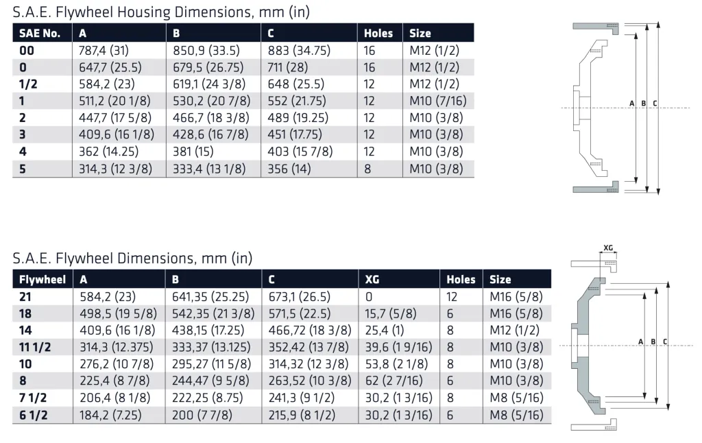
Mounting configurations for single bearing alternators using SAE (Society of Automotive Engineers) sizes are standardized to ensure compatibility between the engine and the alternator. These configurations are crucial for proper alignment and efficient performance. Here’s a detailed explanation of the mounting configurations for single bearing alternators with SAE sizes:
SAE Mounting Flanges and Adaptation
SAE Flange Standards:
- SAE J617: This standard defines the dimensions and specifications for engine flywheel housings and corresponding alternator flanges.
- Common SAE Sizes: The sizes commonly used for single-bearing alternators include SAE 0, 1, 2, 3, 4, and 5. The size number indicates the dimensions of the flange, with lower numbers representing larger sizes.
SAE Flywheel Housing Sizes:
- SAE 0: Typically used for large engines, with a diameter of 20 inches (508 mm).
- SAE 1: Common for medium to large engines, with a diameter of 18.375 inches (467 mm).
- SAE 2: Suitable for medium engines, with a diameter of 16.125 inches (410 mm).
- SAE 3: Used for smaller engines, with a diameter of 14.25 inches (362 mm).
- SAE 4: Smaller engines, with a diameter of 12.375 inches (314 mm).
- SAE 5: Smallest size, with a diameter of 10.375 inches (264 mm).
Mounting Configurations
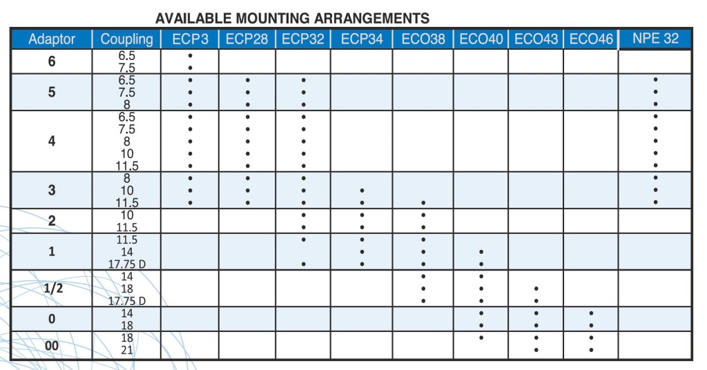
1. Direct Coupling:
- Description: The alternator is directly bolted to the engine flywheel housing using a flange that matches the SAE size.
- Components: This setup typically includes an adapter plate, a flexible coupling, and a centring ring to ensure precise alignment.
- Application: Commonly used in compact generator sets where space is limited and direct drive is preferred for efficiency.
2. Bell Housing Mounting:
- Description: Utilizes an SAE bell housing to connect the alternator to the engine.
- Components: The bell housing serves as an intermediate adapter, allowing for some flexibility in alignment and reducing vibrations. It is mounted on the engine’s flywheel housing and supports the alternator.
- Application: Provides additional vibration isolation and is suitable for applications where slight misalignment might occur.
3. Engine Foot Mounting:
- Description: The alternator is mounted on a base frame or skid that also supports the engine. The entire assembly is bolted together, providing a stable and rigid structure.
- Components: Includes mounting feet, vibration dampers, and flexible couplings to connect the alternator to the engine.
- Application: Used in stationary generator sets where robust support and vibration isolation are critical.
Alignment and Coupling
Flexible Coupling:
- Function: Absorbs minor misalignments and dampens vibrations between the engine and alternator.
- Types: Common types include jaw couplings, disc couplings, and elastomeric couplings, selected based on the specific application requirements.
Adapter Plates:
- Function: Ensure compatibility between the engine’s flywheel housing and the alternator’s flange.
- Customization: Adapter plates are often customized to match different SAE sizes, ensuring a secure and aligned connection.
Installation Considerations
- Alignment Precision: Ensure precise alignment between the engine and alternator to prevent premature wear and tear.
- Vibration Isolation: Use appropriate vibration dampers and flexible couplings to minimize the impact of vibrations.
- Maintenance Access: Design the mounting configuration to allow easy access for maintenance and inspections.
Pulley Calculator
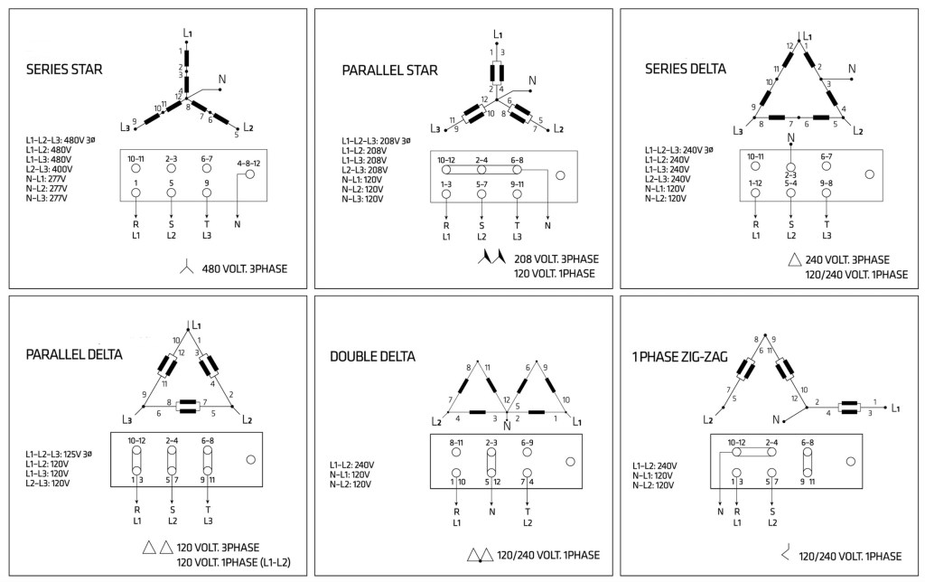
Wiring Connection Diagram
For most applications, an alternator with a 4-wire output (dedicated wiring) is the most efficient and least expensive. Another option is a 12-wire alternator. Twelve wire alternators can be reconfigured as shown in the wiring diagram below. There are terminals on the top of the alternator with labeled wires from the coils connected to them. You can reconfigure them by following the diagram to produce different results.
Share this:
- Print (Opens in new window) Print
- Email a link to a friend (Opens in new window) Email
- Share on Facebook (Opens in new window) Facebook
- Share on LinkedIn (Opens in new window) LinkedIn
- Share on Reddit (Opens in new window) Reddit
- Share on Pinterest (Opens in new window) Pinterest
- Share on Threads (Opens in new window) Threads
- Share on X (Opens in new window) X
- Share on Bluesky (Opens in new window) Bluesky