

MAGNETISM
Magnetism plays a crucial role in generating electricity, and conversely, electricity can generate magnetism. While our understanding of magnetism is not complete, we know certain behaviour patterns that have enabled the creation of devices like generators and motors. The space around a magnet is filled with magnetic lines of force known as “flux,” which concentrate at the magnet’s north and south poles. These lines of force form loops, exiting from the north pole and re-entering at the south pole, without ever crossing each other. The area influenced by these lines of force is called a “magnetic field.” Similar poles repel, while opposite poles attract each other.

ELECTROMAGNETIC FIELDS
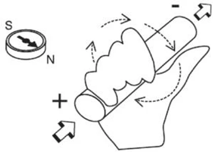
When an electric current flows through a conductor, it generates a magnetic field around the conductor, which is always perpendicular to it. If a compass is placed near the conductor, the needle will align at a right angle to the conductor. The magnetic field’s strength increases with the current flow, and the field is distributed along the conductor’s length. The “right-hand rule” helps determine the direction of the magnetic field: by wrapping your right hand around the conductor with the thumb pointing in the current’s direction, your fingers point in the direction of the magnetic lines of force.
Note: The right-hand rule is based on the conventional current flow (positive to negative), differing from the electron flow theory (negative to positive).
ELECTROMAGNETIC INDUCTION
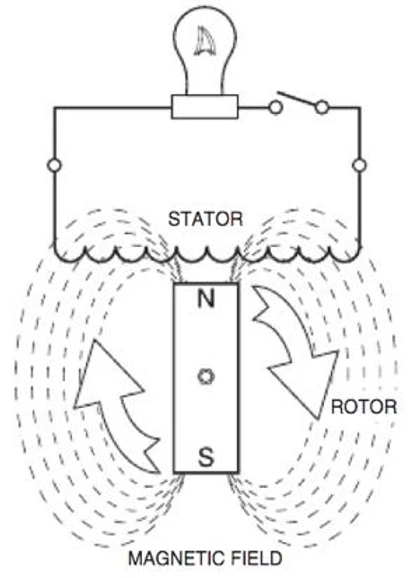
An electromotive force (EMF) or voltage can be produced in a conductor by moving the conductor so that it cuts across the lines of force of a magnetic field. Similarly, if the magnetic lines of force are moved so that they cut across a conductor, an EMF (voltage) will be produced in the conductor. This is the basic principle of the revolving field generator. The figure below illustrates a simple revolving field generator. The permanent magnet (Rotor) is rotated so that its lines of magnetic force cut across a coil of wires called a Stator. A voltage is then inducted into the Stator windings. If the Stator circuit is completed by connecting a load (such as a light bulb), the current will flow in the circuit, and the bulb will light.

A SIMPLE AC GENERATOR
A basic AC generator consists of a rotating magnetic field (rotor) and a stationary coil of wire (stator). The rotor is a permanent magnet with north and south poles. As it turns, its magnetic field cuts across the stator, inducing a voltage in the stator windings. When the north pole of the rotor passes the stator, current flows in one direction; when the south pole passes, current flows in the opposite direction, creating an alternating current (AC) waveform.
In a 2-pole rotor, a single north and south pole pair requires a rotation speed of 3600 RPM to produce a 60 Hz AC frequency or 3000 RPM for a 50 Hz frequency. A 4-pole rotor, with two north and two south poles, needs to operate at 1800 RPM for 60 Hz or 1500 RPM for 50 Hz.
A More Advanced AC Generator
In a more sophisticated generator, a regulated direct current is supplied to the rotor windings via carbon brushes and slip rings, creating a stable magnetic field around the rotor. This field induces a regulated voltage in the stator. The excitation current supplied to the rotor is crucial for maintaining this regulated magnetic field.
The engine drives the rotor at a constant speed, managed by a mechanical governor. For a 2-pole rotor, this speed is set to approximately 3720 RPM without load, ensuring an AC output frequency close to 62 Hz to prevent significant droop under heavy loads.
When an electrical load connects to the stator power windings, current flows through the circuit, and the rotor’s magnetic field induces voltage into the stator’s battery charge windings. This AC output is converted to DC by a battery charge rectifier (BCR) to keep the battery charged.
Residual magnetism in the rotor is sufficient to induce a small voltage in the stator’s AC power windings. During startup, the engine controller circuit board supplies battery voltage to the rotor, enhancing the magnetic field through “Field Boost.” This combination of residual and boosted magnetism induces a voltage in the stator windings. The excitation winding’s unregulated AC output is delivered to an electronic voltage regulator, which maintains the actual voltage at a preset reference level by adjusting the current flow to the rotor.
Voltage Regulation
The voltage regulator compares the actual sensing voltage from the stator AC power windings with the preset reference voltage. If the actual voltage exceeds the reference, the regulator decreases the current flow to the rotor; if it falls short, the regulator increases the current flow. This regulation ensures the voltage remains consistent with the preset reference, providing a stable output.
Note: The voltage regulator also converts the AC output from the stator excitation windings to DC, ensuring the generator operates efficiently and reliably.
Share this:
- Print (Opens in new window) Print
- Email a link to a friend (Opens in new window) Email
- Share on Facebook (Opens in new window) Facebook
- Share on LinkedIn (Opens in new window) LinkedIn
- Share on Reddit (Opens in new window) Reddit
- Share on Pinterest (Opens in new window) Pinterest
- Share on Threads (Opens in new window) Threads
- Share on X (Opens in new window) X
- Share on Bluesky (Opens in new window) Bluesky