How it works
Automatic transfer switches (ATS) are commonly used in standby generator setups. They are designed to detect any power outage or disturbance in the primary power source. An ATS has a built-in mechanism that monitors the presence or absence of electricity from the primary source. When the primary power fails or drops below a certain threshold, the transfer switch sends a signal to the generator to start. Once the generator is stable, the transfer switch switches to the backup power source.
How the signal is sent to the generator
The transfer switch opens and closes a relay contact inside the transfer switch that the generator monitors to see if the connection is made. When the two wires are connected, the generator knows it should start or stop, and the controller on the generator takes care of the rest. It does not matter what the polarity is of the two wires. Still, because it is low voltage (DC), those wires shall never be run inside the same conduit as any AC power lines, or interference will affect the signal, and it’s against the electrical code to do so anyway.
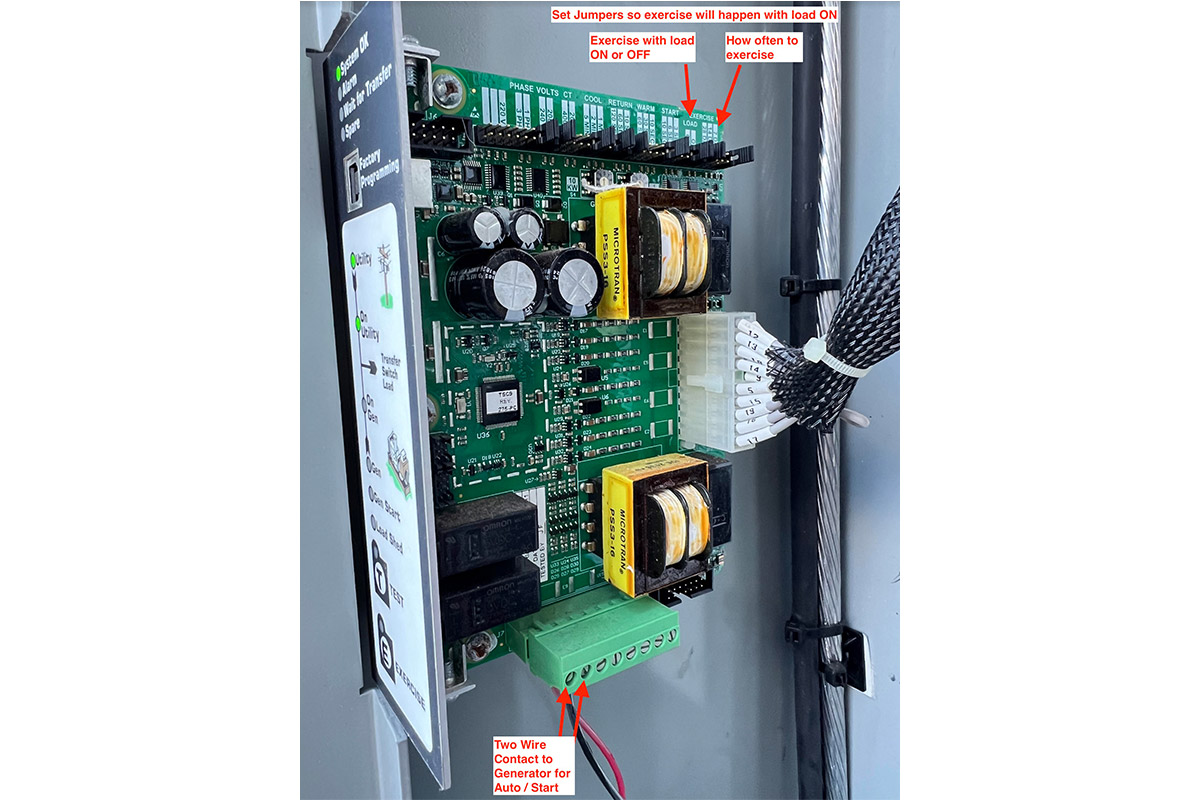
On Thomson transfer switches this connection is made as shown in the image below. It is the first two terminals on the bottom of the ATS controller. Here someone used a red and black wire but it does matter what you use nor the polarity. It can be in reverse and it will still work.

Generator ATS Connections
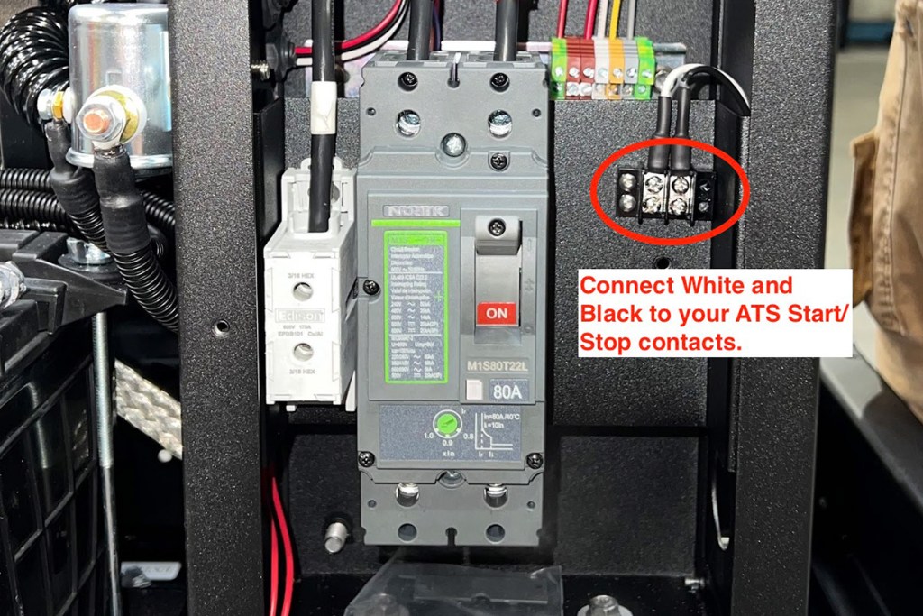
On the generator side, the genset controller is configured to look for the connection of two wires. The controller will know there is a call to start the generator if they are connected. If it is disconnected, the generator controller knows there is a call to turn off the generator. As of 2023/2024, the two wires are connected to the terminal block next to the main circuit breaker. Your main circuit breaker may look different than the one shown, but the two wires are still located next to it, as shown below.
Setting up Exercising
Modern automatic transfer switches come with a pre-set schedule for exercising the generator. However, setting up a schedule for exercising the generator controller alone is not recommended. This is because the transfer switch will not connect your home to the generator running if there is no power failure. If you want to run the generator while having power, it is best to do so through the transfer switch. It can switch power over to the generator without any noticeable delay, allowing your generator to work during the test rather than just running without doing any work. Running generators under 30% load can result in long-term damage from deposits and varnishing of cylinder walls. It’s better to exercise the generator and have it work during that period.
ATS Wiring
Only two wires are required to signal the generator to start or stop. The transfer switches are responsible for opening or closing the connection between these two wires from the generator. The generator controller is configured to monitor the status of one of its inputs to determine whether it is grounded or ungrounded. The automatic transfer switch’s role is to establish or break that connection. Based on this open or closed connection, the generator controller knows whether to start or stop. These two lines are one ground and one sensor input, both DC and low voltage. They are also known as control wires.
Control wires must not be run in the same conduit as AC power lines from or to your generator.
Here are a few reasons why it’s often advised to keep AC and DC wires separate:
- Interference: AC and DC currents can cause interference with each other when they run in the same conduit. This interference might lead to signal distortion or noise in the control circuits, affecting the proper functioning of the control systems.
- Safety Concerns: Mixing AC and DC in the same conduit can increase safety risks. There’s a possibility of induction or induction heating in the wires due to the varying currents and voltages. This can create hazards like overheating, which might lead to electrical failures, insulation damage, or even fires.
- Code Compliance: Electrical codes and regulations often specify the segregation of AC and DC wires for safety and performance reasons. Following these codes is crucial for ensuring a safe and compliant electrical installation.
Maintaining safety and preventing interference is advisable by keeping AC and DC wiring separate during installation. Different conduits or paths should be used for each type of wiring. In cases where they must cross paths or be nearby, appropriate shielding, insulation, or separation methods prescribed by electrical codes should be used to mitigate potential problems. It is essential to consult with a qualified electrician or follow local electrical codes and regulations when planning the installation of AC and DC wiring.
Share this:
- Click to print (Opens in new window) Print
- Click to email a link to a friend (Opens in new window) Email
- Click to share on Facebook (Opens in new window) Facebook
- Click to share on LinkedIn (Opens in new window) LinkedIn
- Click to share on Reddit (Opens in new window) Reddit
- Click to share on Pinterest (Opens in new window) Pinterest
- Click to share on Threads (Opens in new window) Threads
- Click to share on X (Opens in new window) X
- Click to share on Bluesky (Opens in new window) Bluesky